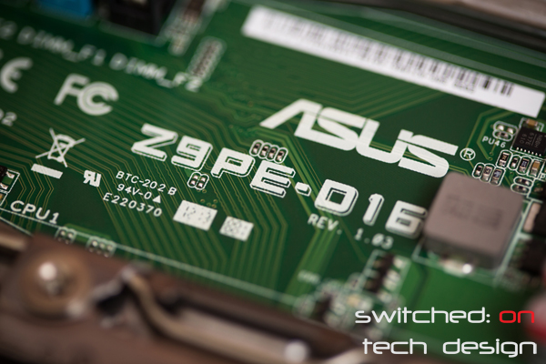
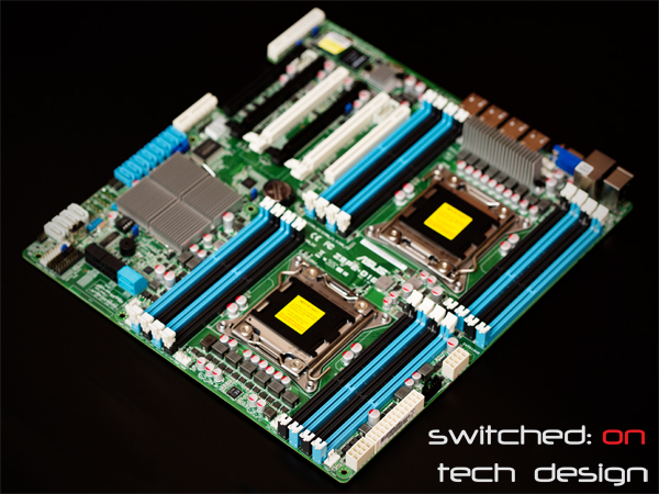
Up for review today we have one of Asus’ dual-socket-2011 server motherboards – the Z9PE-D16. Hit the break to find out what it’s all about and why you might care about it even if you don’t need to run two CPUs…
In a nutshell, the Z9PE-D16 is a dual-socket 2011 server-oriented motherboard, featuring the C602-A chipset. It’s certainly not a small board, conforming to the SSI EEB form factor:
Other important specs include:
16 RAM slots (maximum capacity of 512GB (!) registered memory)
PCI-Express version 3.0
4 x16 slots
2 x8 slots
Additional x4 Pike-specific SAS port slot
SSI EEB form factor (12×13″)
ASWM Enterprise (remote control via dedicated LAN port)
2x 6gb/s SATA ports
8x 3gb/s SATA ports
Quad Gigabit Ethernet via i350-AM4 controller
Dedicated Management LAN port
AST2300 on-board graphics w/VGA out
8x 4-pin fan headers
2x serial port headers
Internal USB port
PS2/USB ports
…and plenty more. As you can see it’s an incredibly feature-rich motherboard; the PIKE cards are actually quite reasonably priced at $200 for the LSI2008-based card. That card can also be flashed to IT mode like an IBM M1015 card, meaning that it’s quite useful for a storage server – so long as it’s being used with spinning disks, though, as the x4 slot may be restrictive if you attach too many SSDs to a controller on it.
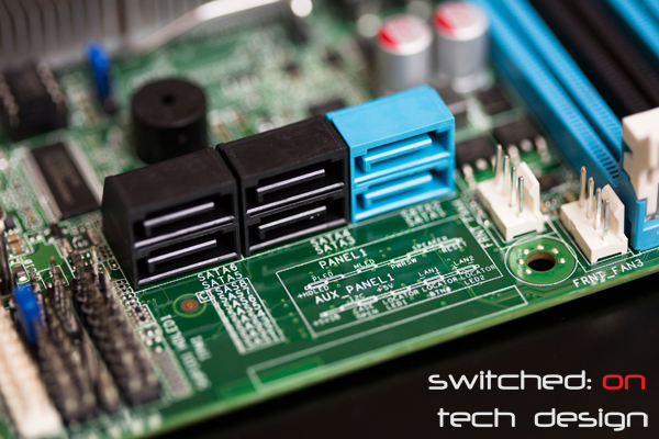
Above you can see the standard SATA ports coming from the C602 chipset; the two blue ports are 6gb/s and the four black ports are 3gb/s. Running parallel to the board can be a little awkward for plugging/unplugging cables when the board is in a chassis but it really helps airflow to not have cables sprouting up from the board, so we feel it’s a worthy trade-off. To the right you can see two of the eight fan headers – a very nice addition to the board and likely more than most people will need.
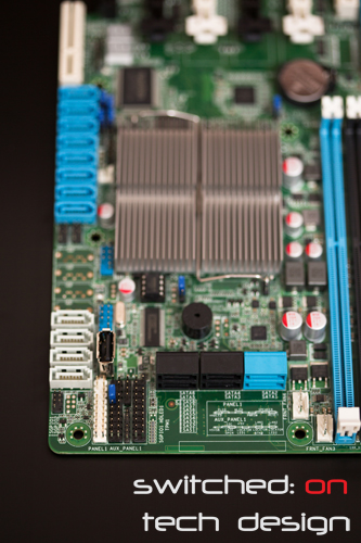
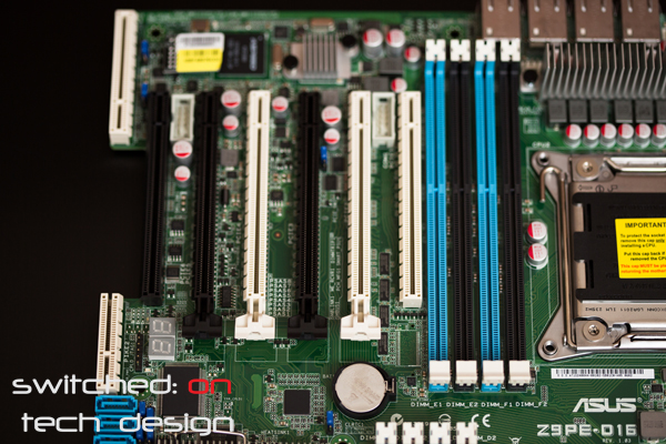
The blue ports against the edge of the board behind the 3gb/s ports are the optional onboard SAS ports; with the addition of an Asus PIKE module these are activated and give you 8 6gb/s SAS ports. The PIKE controller sits against the edge of the chassis, as you can see here on the left:
You’re sure not going to be accidentally plugging a regular PCI-Express card into the PIKE slot. To the right of the PIKE slot you can see the diagnostic readout dual-digit display; this is quite handy when you’re setting up the server as you can see at what point it stalls if you have an issue. The white PCI-E slots are connected to CPU1, the black to CPU2. The PIKE, being white, is also hooked up to CPU1. On the far side you can see the two serial headers between the leftmost black slots and the rightmost white slots, conveniently close to the rear of the chassis – too many consumer boards have serial headers on the opposite end of the board, requiring unusually long serial cables to have them reach the rear of the chassis. Nice to see some thought going into their placement.
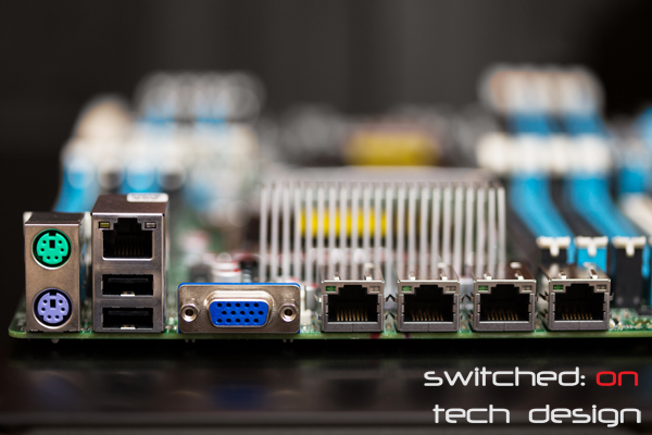
Moving around the board to the rear I/O panel, we have the PS/2 keyboard and mouse connectors (purple for keyboards, green for mice), two USB 2.0 ports and the dedicated management Ethernet port, the VGA out and then the four gigabit connectors from the i350 controller. Pretty bare-bones compared to most consumer boards but more than adequate for a server board. If you need more USB ports there are multiple USB 2.0 headers internally; you’ll just have to find somewhere to break them out to.
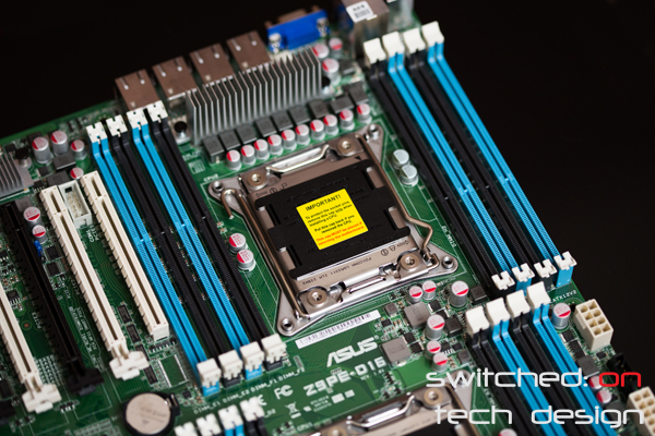
Moving further around the board we come to CPU2 – the CPU socket closest to the I/O panel. Note that the left-most RAM slot is quite close to PCI-E slot #1 – it’s worth making sure that the card you intend on putting there doesn’t need any additional clearance above the slot. The RAM slots are Asus’ typical single-latching type, which does make it easy to add or remove RAM once the board is already in place.
Here we have CPU socket 1. Nothing really all that different to the other socket, unsurprisingly. There’s another 4-pin fan connector just inside of the left-most RAM slots, too. The power connectors may be a little different to what you’re used to, however:
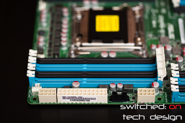
The standard 24-pin power connector is flanked by two 8-pin CPU power connectors – if you’re thinking of using this board make sure your PSU is capable of supplying this combination. Note that 8-pin PCI-E connectors are not compatible with the CPU ones! There’s another 4-pin fan connector hiding away on the left side of the board here, too.
So, that’s an overview of the board itself… stay tuned for Part Two where we put it all together in a system and explore an unexpected board feature – the aforementioned reason why you might care about this board even if you don’t need two CPUs…
You can buy the Asus Z9PE-D16 from Amazon.com:
